Four Quadrant Regenerative Charging
Four Quadrant Operation of DC Motor
Four Quadrant Operation of any drives or DC Motor means that the machine operates in four quadrants. They are Forward Braking, Forward motoring, Reverse motoring and Reversebraking. A motor operates in two modes – Motoring and Braking. A motor drive capable ofoperating in both directions of rotation and of producing both motoring and regeneration is calleda Four Quadrant variable speed drive.
In motoring mode, the machine works as a motor and converts the electrical energy into mechanical energy, supporting its motion. In braking mode, the machine works as a generator and converts mechanical energy into electrical energy and as a result, it opposes the motion. The Motor can work in both, forward and reverse directions, i.e., in motoring and braking operations. The product of angular speed and torque is equal to the power developed by a motor. For the multi-quadrant operation of drives, the following conventions about the signs of torque and speed are used. When the motor is rotated in the forward direction the speed of the motor is considered positive. The drives which operate only in one direction, forward speed will be their normal speed.
In loads involving up and down motions, the speed of the motor which causes upward motion isconsidered to be in forward motion. For reversible drives, forward speed is chosen arbitrarily.The rotation in the opposite direction gives reverse speed which is denoted by a negative sign.The rate of change of speed positively in the forward direction or the torque which providesacceleration is known as Positive motor torque. In the case of retardation, the motor torque isconsidered negative. Load torque is opposite to the positive motor torque in the direction.
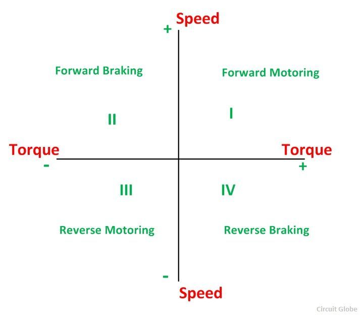
In the I quadrant power developed is positive and the machine is working as a motor supplying mechanical energy. The I (first) quadrant operation is called Forward Motoring. II (second) quadrant operation is known as Braking. In this quadrant, the direction of rotation is positive, and the torque is negative, and thus, the machine operates as a generator developing a negative torque, which opposes the motion.
The kinetic energy of the rotating parts is available as electrical energy which may be supplied back to the mains. In dynamic braking, the energy is dissipated in the resistance. The III (third) quadrant operation is known as the reverse motoring. The motor works, in the reverse direction. Both the speed and the torque have negative values while the power is positive.
In the IV (fourth) quadrant, the torque is positive, and the speed is negative. This quadrant corresponds to the braking in the reverse motoring mode.
Four-Quadrant Chopper (or Class E Chopper)
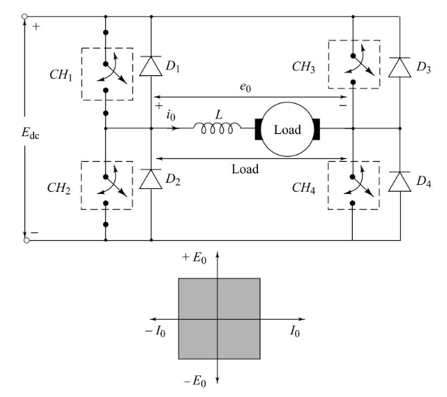
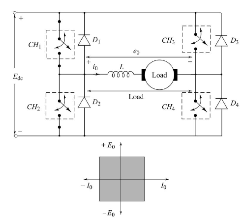
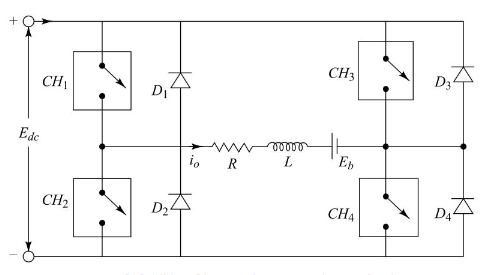
Figure below shows the basic power circuit of Type E chopper. From Fig. below, it is observed that the four-quadrant chopper system can be considered as the parallel combination of two Type C choppers. In this chopper configuration, with motor load, the sense of rotation can be reversed without reversing the polarity of excitation. In Fig. below, CH1, CH4 D2 and D3 constitute one Type C chopper and CH2, CH3, D1 and D4 form another Type C chopper circuit. Figure below shows Class-E with R-L load.
If chopper CH4 is turned on continuously, the antiparallel connected pair of devices CH4 and D4 constitute a short-circuit. Chopper CH3 may not be turned on at the same time as CH4 because that would short circuit source Edc. With CH4 continuously on, and CH3 always off, operation of choppers CH1 and CH2 will make E0 positive and I0 reversible, and operation in the first and second quadrants is possible. On the other hand, with CH2 continuously on and CH1 always off, operation of CH3 and CH4 will make E0 negative and I0 reversible, and operation in the third and fourth quadrants is possible.
The operation of the four-quadrant chopper circuit is explained in detail as follows:
When choppers CH1 and CH4 are turned-on, current flows through the path, Edc+ - CH1 - load - CH4 - Edc. Since both E0 and I0 are positive, we get the first quadrant operation. When both the choppers CH1 and CH4 are turned-off, load dissipates its energy through the path load D3 - Edc+ - Edc- - D2 - load. In this case, E0 is negative while I0 is positive, and fourth-quadrant operation is possible.
When choppers CH2 and CH3 are turned-on, current flows through the path, Edc+ - CH3 - load - CH2 - Edc-. Since both E0 and I0 are negative, we get the third-quadrant operation. When both choppers CH2 and CH3 are turned-off, load dissipates its energy through the path load- D1 - Edc+ - Edc- - D2 - load. In this case, E0 is positive and I0 is negative, and second-quadrant operation is possible.
This four-quadrant chopper circuit consists of two bridges, forward bridge and reverse bridge. Chopper bridge CH1 to CH4 is the forward bridge which permits energy flow from source to load. Diode bridge D1 to D4 is the reverse bridge which permits the energy flow from load-to-source. This four-quadrant chopper configuration can be used for a reversible regenerative d.c. drive.
Buy full version to unlock all the content & features
